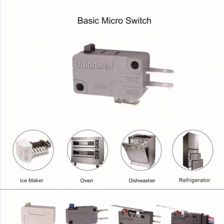
How To Increase Microswitch Life In End Use

Snap-acting switches are designed for long life. By understanding the application factors that affect switch life and applying this knowledge, the maximum switch life can get. Without this understanding, the user could inadvertently shorten switch life.
The Nature Of Switch Life
Switch life functions several variables in switch design, manufacturing, and end-use. A change of any one of these variables can alter the life of the switch. For this reason, a switch life figure has meaning only if it is accompanied by a statement of the conditions under which it applies. The application variables that have the most significant effect on switch life are circuit parameters, actuation, the environment, and the failure criteria. Given that a snap-acting switch is designed for long life, what can the user do to take maximum advantage of this feature? End-use variables can be classified under the headings of electrical, mechanical, and environmental factors. Several ways to prolong switch life are described below:
Electrical Factors Voltage:
In some instances where a switch is used to control a 480 volt AC load, the circuit can be arranged so that the switch performs the required function but controls only 120 volts. Usually, the contact life of a switch is about the same at 240 as at 120 volts AC and is only somewhat reduced at 480 volts. However, the probability of dielectric breakdown increases with the supply voltage, and switch life is appreciably longer at lower voltages.
Current:
As a rule, the lower the current, the longer the switch life. Therefore, reducing the current that the switch must close and open usually increases the life of the switch. There are exceptions, such as where spring life is the limiting factor or the rate and direction of contact material migration must be controlled. Circuits with high inrush current may limit switch life by contact erosion or welding. If the inrush is due to tungsten filament lamps or vacuum tubes, a resistor can be connected in parallel with the switch to keep the filaments warm and reduce the inrush current. Of course, This draws some current when the switch is open. If this is objectionable, a resistor or thermistor in series with the filament can reduce inrush current.
Arc Control:
The less severe the arc, the longer the life of the switch contacts. The most severe arcing usually is encountered in DC inductive circuits. Here the energy stored in the field is partially dissipated in the arc. Several arc suppression techniques are available. One simplest and most effective is a diode connected in a blocking mode across the DC coil. When the switch opens, the polarity of the voltage induced in the coil opposes that of the steady-state condition, and the diode conducts, shorting the coil. This can significantly reduce arc energy at the switch contacts and give a corresponding increase in switch life. The diode can be of much lower current capacity than the steady-state current of the load because the diode conducts only for a short time. The diode should have a peak inverse voltage rating exceeding the source voltage. Using a diode will delay the drop-out time of the inductive device by a few milliseconds, but this is usually acceptable. The arc suppression device should be tested to confirm its suitability. This way, reducing the arcing can significantly extend switch life by reducing the rate of contact material migration and decreasing the heat dissipated by the arc.
Choice Of Throw:
The normally closed throw of a snap-acting switch can break contact welds more than the ordinarily open it because of the nature of the switch mechanism. If a circuit has a high inrush current on closure or requires the switch to open current near its rated load, switch life is likely to be longer if the ordinarily closed throw is used to control the circuit.
Grounding:
Switches often are mounted on a surface or bracket that is electrically grounded. In many cases, this is desirable or necessary for safety. In others, it is optional. Suppose the mounting is connected to a standard electrical ground with the power supply. In that case, line voltage will be maintained between the current-carrying parts of the switch and the mounting surface. This applies continuous electrical stress and encourages dielectric breakdown as switch life proceeds. The electrical ratings of switches are established with the mounting grounded to provide “worst-case” conditions. However, if the switch is mounted on an insulator in end-use and actuated with an insulating member, the life of insulating parts will be prolonged.
Mechanical Factors
- Actuate the switch coaxially with the plunger, if possible. If not, use a roller plunger or roller lever type switch to prolong the life of the plunger bearings.
- Avoid impact actuation and drop-off or snap release of the switch plunger.
- The life of the switch mechanism can be increased by reducing the travel of the plunger, but if the current is high, do not reduce plunger travel to the point where contact welding becomes a problem. If the life of the switch is limited by contact welding, drive the plunger to full overtravel and full release.
- Do not apply excessive force to the plunger at full overtravel.
- If the switch controls heavy electrical loads, actuation frequency should be no higher than 20 operations per minute on DC loads or 60 operations per minute on AC.
For more can contact us a mail to: marketing@unionwellswitch.com.